Smart Slope Generator — Automate Slope Hatching in AutoCAD & Civil 3D (Free)
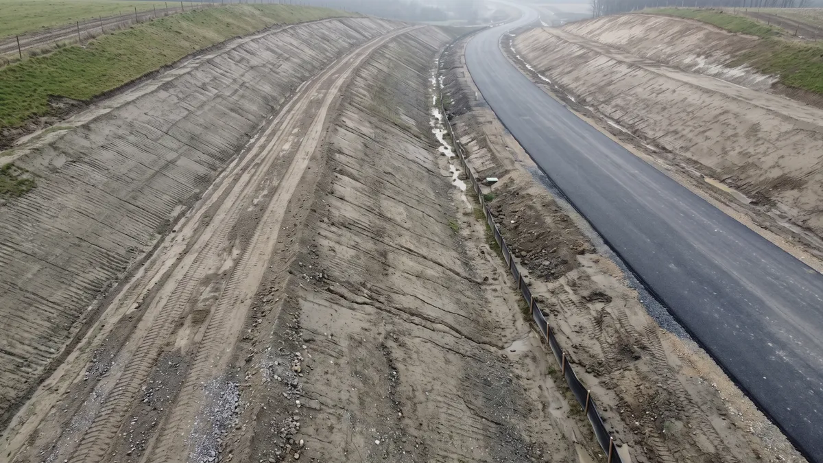
In civil earthwork and site grading projects, clear documentation is not optional. Representing cut and fill slopes with standard batter lines (slope ticks) between the top of bank and the toe of slope is a mandatory drafting standard on almost every set of grading drawings. Executing that task manually with native CAD tools — array, rotate, trim, repeat — is one of the slowest and least valuable jobs in the entire production chain.
To remove that bottleneck, we developed the Smart Slope Generator: a free plugin for AutoCAD, Civil 3D, ZWCAD and GstarCAD that generates standardized slope symbology between any two selected boundaries.
The Manual Problem
Manual slope hatching fails in three predictable ways:
- Time: a single embankment along a road alignment can require hundreds of individual strokes, each one perpendicular to a reference line and stopping exactly at the toe.
- Consistency: arrayed and trimmed linework drifts. Spacing varies between drawings, between drafters, and between revisions of the same sheet.
- Rework: when the grading design moves — and it always moves — the entire hatch pattern is redrawn from zero.
How Smart Slope Generator Works
The tool runs from the typed command GR_DRAWSLOPE (short alias DRAWSLOPE), or from the Smart Slope button on the Add-ins ribbon tab. In ZWCAD the button sits on the GR Tools tab; in GstarCAD the command is typed.
- Run
GR_DRAWSLOPE. The settings window opens. - Set the pattern, layers and options, then click Draw Slope.
- Pick the TOP line (crest / shoulder), then the BOTTOM line (toe).
- Entire mode hatches the full length; Segment mode hatches only a dragged portion.
- A live preview appears. Press ENTER to draw.
- The prompts loop straight into the next slope. ESC returns to the settings window.
Lines, polylines, 3D polylines, arcs, circles, ellipses and splines are all accepted as boundaries — the tool is not restricted to feature lines.
The Alignment: Which Line Drives the Spacing
One of the two picks acts as the alignment — the line along which tick spacing is measured, like chainage along a road. The other line simply receives the far end of each stroke, square-on. The Perpendicular to setting decides which is which:
- Perpendicular to: Bottom line (Toe) — strokes land square to the bottom line, so the TOP line is the alignment and spacing is even along the top. Default, and the better choice for cut slopes.
- Perpendicular to: Top line (Crest) — strokes land square to the top line, so the BOTTOM line is the alignment and spacing is even along the bottom. Better for fill slopes.
None of this has to be memorized: every prompt names its role, the choice is confirmed on the command line after both picks, and the alignment carries a thick highlight overlay on screen for the whole operation. Practical tip: make the shorter of the two lines the alignment. If the alignment runs well past the other line's end, strokes near the overrun bunch onto a single endpoint — the Skip overlaps option removes them automatically.
Pattern Control
The Settings panel covers the drafting convention itself:
- Hatch Pattern Step — the distance between neighbouring strokes, measured along the alignment, in the drawing's own units.
- Offset from Toe — shortens every stroke at its far end, leaving a clean strip along the toe line.
- Short stroke length — the length of a short stroke as a percentage of the full crest-to-toe distance at that position.
- Pattern Style — Fixed (all strokes full length), Long / 1 Short, or Long / 2 Shorts (the common European drafting convention).
Layer and Colour Standards
The Appearance panel maps output onto three rows: Cut, Fill and Generic. The defaults are C-TOPO-SLOPE-CUT, C-TOPO-SLOPE-FILL and C-TOPO-SLOPE, and each is an editable dropdown — pick an existing layer or type a new name and it is created when you draw.
Colour defaults to ByLayer, the correct behaviour for CAD standards compliance: the strokes follow the layer, now and whenever the layer is restyled later. A per-row Override option exists for the case where an existing layer should deliberately be repainted — and it resets every time the window opens, so a one-off decision never becomes a permanent rule. If a chosen layer is frozen, off or locked, a warning appears before the strokes disappear into it.
Options That Matter on Real Projects
- 3D Slope Lines: strokes carry the real elevations of the picked lines — correct for surfaces and 3D models. Switch off for flat 2D output at elevation 0.
- Cut/Fill Auto Orient: compares elevations at every stroke, points the tick downhill, and splits the output onto the Cut and Fill layers automatically.
- Background hatch: a semi-transparent mask filling the band between the two lines, its boundary following the real vertices and curves of the geometry. Sent to the bottom of the draw order so it never covers linework.
- Triangle (Tapered) Base: draws each long stroke as a filled tapering wedge, Civil 3D style, with an adjustable base width.
- Short Line Ending: None, Circle, or Tick (T-shape) at the free end of short strokes.
- Group Objects: each slope becomes one AutoCAD group, so a single click selects the whole slope.
Manual Adjustment Where Automation Is Not Enough
The automatic rule sends each stroke to the nearest point on the opposite line. That is correct most of the time, but sharp corners and uneven survey geometry sometimes need a different distribution. After the picks, click a start preview stroke, click an end preview stroke, and drag: the strokes in that range spread evenly between the start point and the point being dragged, with the preview updating live. A manually adjusted range always overrides the automatic rule, and where two adjustments overlap the newest drag wins.
The Preview Is the Real Engine
The preview panel is not an illustration. Every change in the window is fed through the same calculation that draws in AutoCAD, over a built-in sample terrain with a cut side and a fill side. Pattern, ratio, taper, endings, colours, mask and the Skip-overlaps behaviour all display exactly as they will be drawn. The single exception is spacing: the preview clamps its own stroke spacing to a readable range so that a very small or very large Step does not turn the fixed-size picture into an unreadable smear. The value entered is used unchanged in the actual drawing.
Built-in Safety Limits
Automation without limits is a hazard. If a long line combined with a small Step would generate enough strokes to freeze AutoCAD, the command refuses the job and reports the estimated count instead of drawing it — increase the Step, or use Segment mode on a shorter range. Jittery survey polylines carrying thousands of near-duplicate points are cleaned up on an in-memory copy; the actual drawing objects are never modified.
Supported Versions
One installation package covers AutoCAD 2024 through 2027, including Civil 3D and other AutoCAD verticals. Windows 64-bit only. AutoCAD 2021–2023 are not supported: the plugin is built against the AutoCAD 2024 programming libraries, and Autodesk guarantees compatibility forwards, not backwards.
It Is Free
Smart Slope Generator is free, and will remain free. No licence, no key, no activation — nothing to purchase, register or unlock. If someone charges for this plugin, they are not us.
Smart Slope Generator removes a tedious manual dependency from grading plan production. Drafting hours drop, slope symbology stays consistent across every sheet in the set, and the engineering team spends its time on the geometric accuracy of the grading design instead of on arraying tick marks.